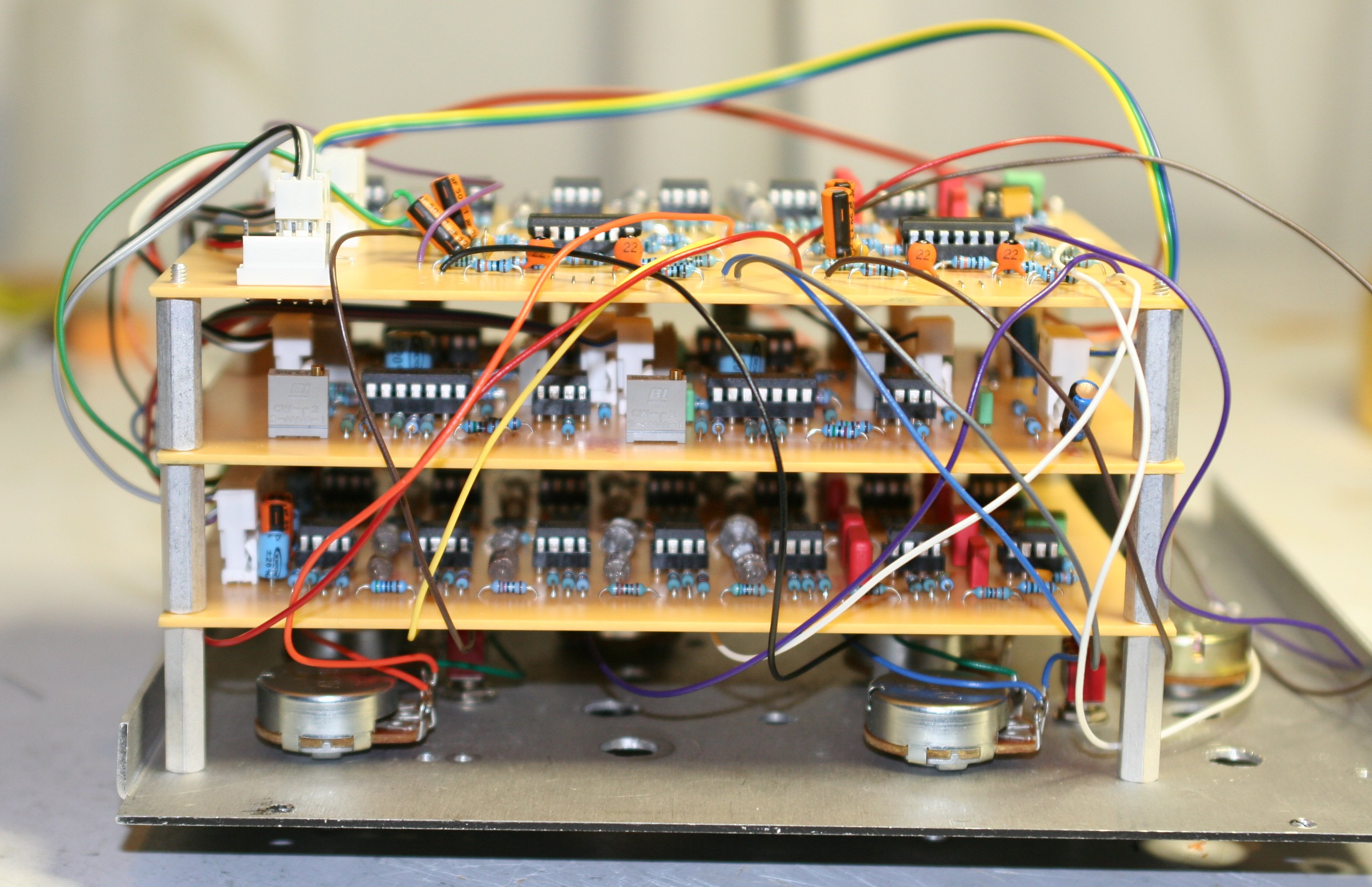
My Prototype Klangumwandler No. 2
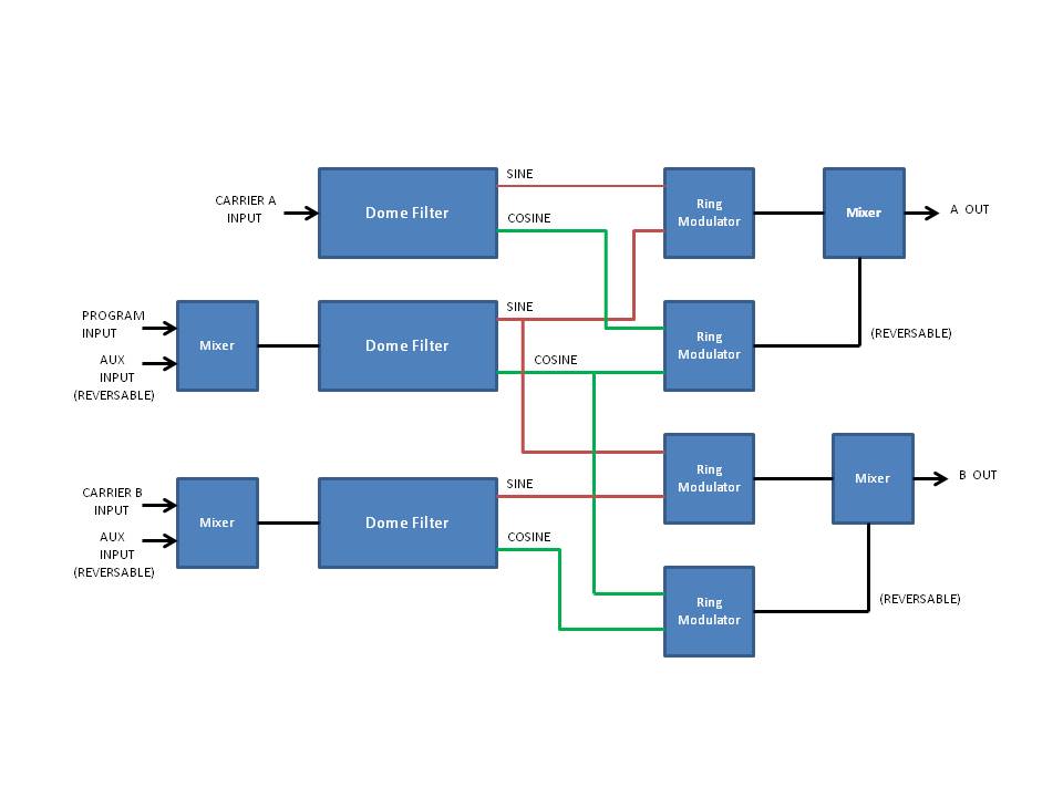
Block Diagram Of My Prototype
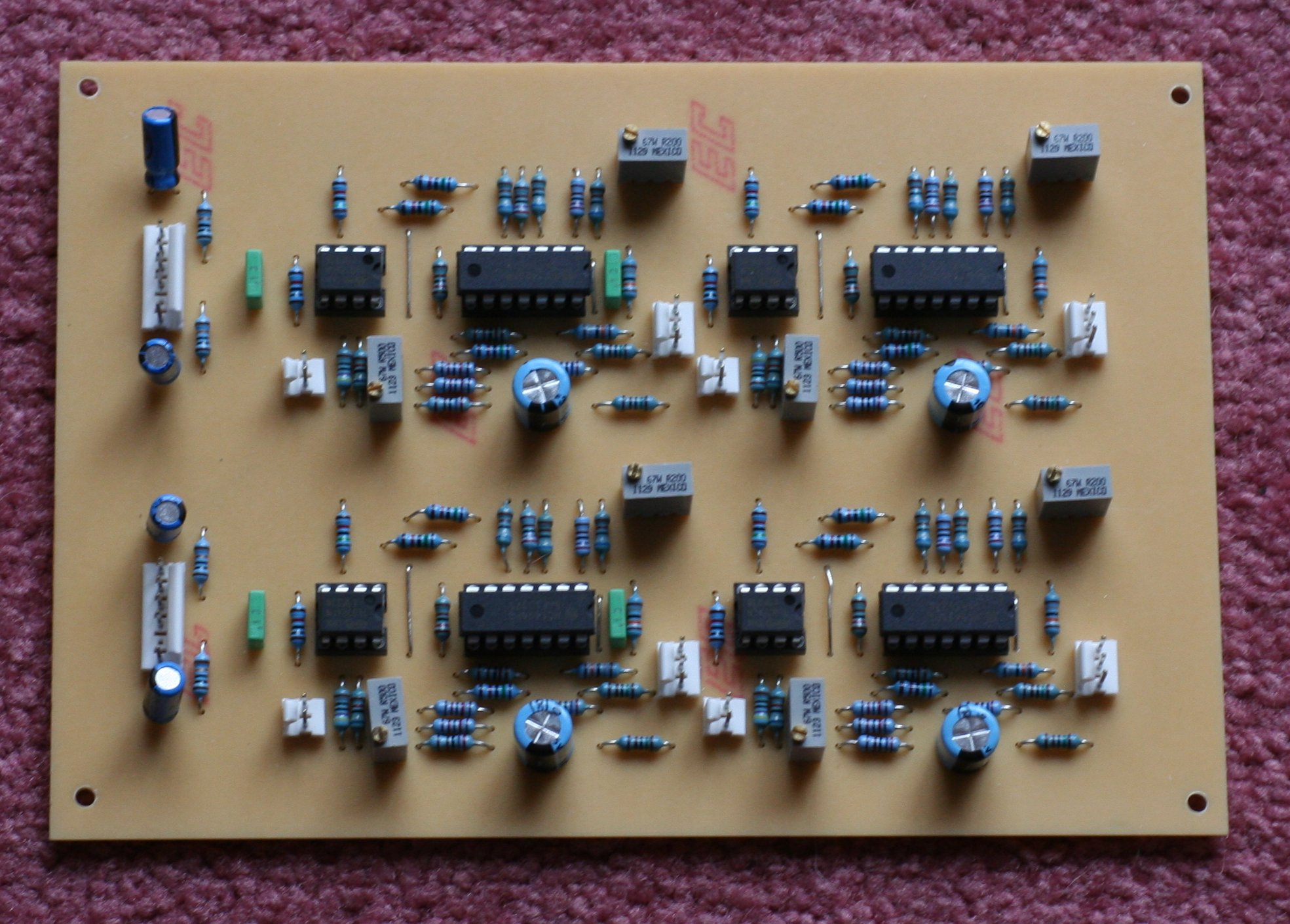
The Dome Filter Board
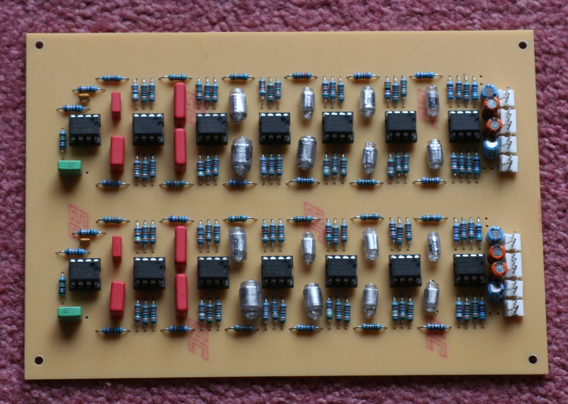
The Balanced Modulator Board
|
Harald Bode Klangumwandler No. 2 |
|
The Klangumwandler No. 2 is basically 2 (or more) conjoined frequency shifters, one "master" and one or more "slaves", sharing a common "program" input. All the necessary design stuff is scattered about the web, and you can see most of it here. It's really a module of modules: 3 dome filters, 4 ring modulators and some summing/differencing amps (mixers). Each additional slave requires an additional dome filter, pair of modulators, and mixers. I built my prototype as one "master" and one "slave". I used more modern circuits - mainly the dome filter that J³rgen Haible used in his frequency shifters, and the 1496 based ring-modulator design by Yves Usson, with its excellent signal nulling. I opted to invert one of the ring modulator outputs rather than swap the sine and cosine inputs, to switch between up and down shifting. I left out the "squelch" initially, and for strictly synth use I don't think it's that useful, but I may eventually throw it in. I haven't tried anything but VCOs (sine and triangle) as inputs yet, and the sounds I'm getting from it are amazing! You would think cross-modulating 3 oscillators would be a total mess, but it can be very musical since you only get the single sidebands Here is a Sound Sample with a sequencer controlling the "program" oscillator, starting with both "carrier" oscillators tuned to unison. A lot of playing around with the 2 carrier frequencies, and swithching from "up shift" to "down" shift about halfway through. Sine output used for all 3 oscillators. Both outputs fed through a VCA with a short attack medium decay envelope. No filters, reverb or anything else in there. Here is another Sound Sample again with a sequencer controlling the "program" oscillator, starting with both "carrier" oscillators tuned to unison. The 2 carrier oscillators are controlled from a split keyboard. The triangle wave outputs of the 2 carrier oscillators and the program oscillator were recorded on the left channel, the Klangumwandler outputs on the right channel. Same VCA envelope on the Klangumwandler, no other audio processing. Both shifts are set to "down Shift", so the Klangumwandler outputs are "retrograde" to the program input. |
|
|
|
|
|
|
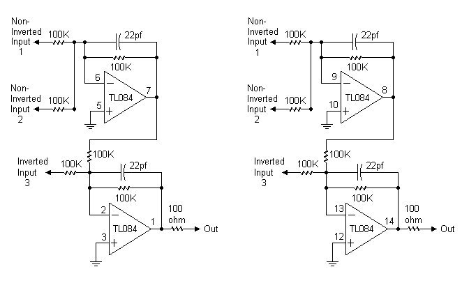
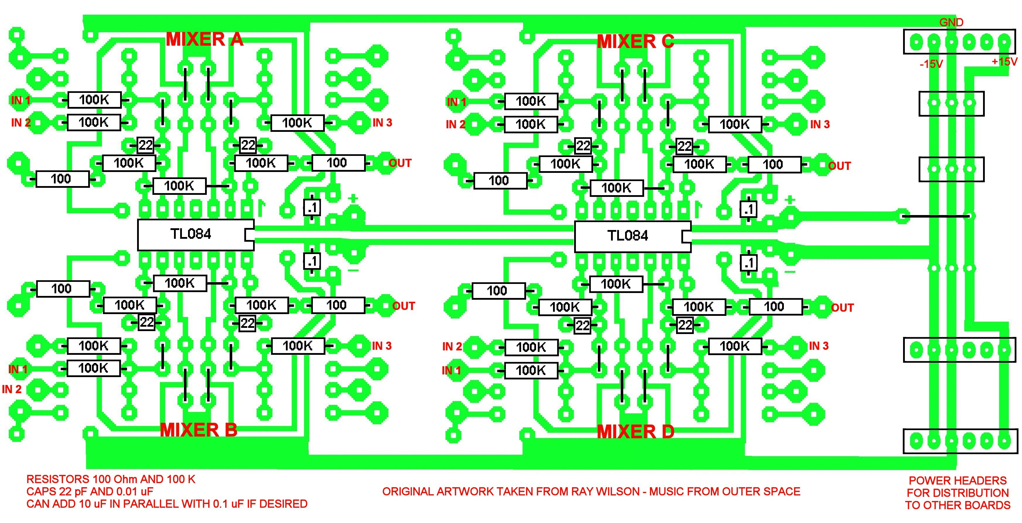
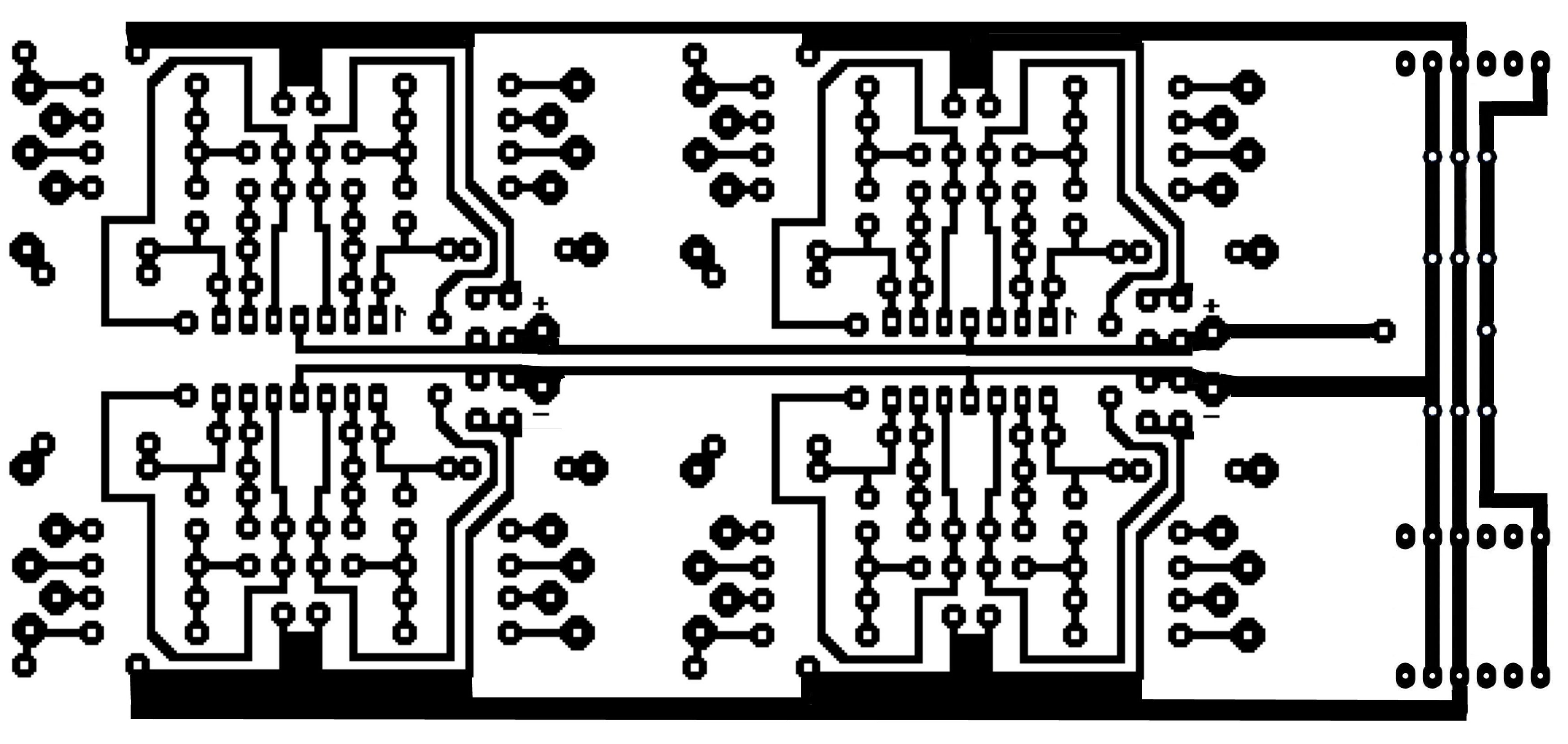
Dome Filters I used J³rgen Haible's Dome Filter layout from his earlier Matrix FX. I etched 2 of them on one board, and the 3rd one on another board with the 4 mixers. It's pretty much the same circuit as the one in Electronotes, and used by Ken Stone for his CGS-45. The CGS-45 Dome Filter will work just as well, without the hassle of etching and drilling a PCB. The CGS-45 Dome filter cand be found here. J³rgen Haible Dome Filter PCB Layout J³rgen Haible Dome Filter Parts Placement This link will take you to J³rgen 's page for building his FA-1 Frequency Shifter, where he gives instructions for measuring the capacitors and selecting the corresponding resistance for each stage of the dome filter in the FS-1. The method (and even the time constants) are the same for this layout as well as the CGS-45. So the spreadsheet will work for both. J³rgen's Spreadsheet for calculating resistors Rx and Ry Balanced Modulators For these I used the Dual Balanced Modulator PCB layout from Yves Usson's website, 2 of them on one board. The page is here. PCBs for this can be purchased from Scot Deyo at The Bride Chamber here. Mixers I used the Music from Outer Space DC Mixer layout, in the "Synth DIY" section under "MFOS Oldies But Goodies". It's a dual mixer, so I combined 2 of them (along with a power distribution bus) on one board. There are 4 mixers: 2 for the combining of the ring modulator outputs for each output, one of which can be inverted (this determines up & down shift)One to mix the Program input and Aux Program input (which can be inverted) One to mix 2 inputs for the "slave" carrier input, also with one that can be inverted. The Aux inputs allow the outputs to be fed-back to the inputs. |
|
|
|
|
More to come . . .